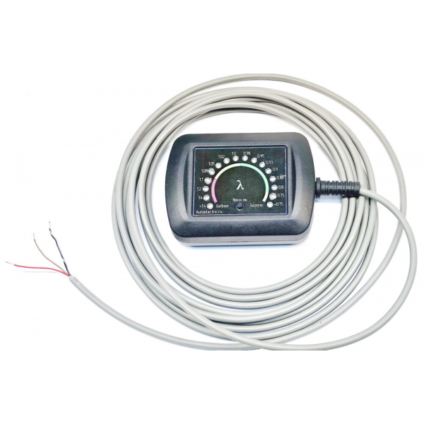
Alfametr provides a visual indication of the current air–fuel mixture in petrol engines with fuel injection or carburettors. Its microprocessor digitises the oxygen-sensor output, measures it and displays the calculated excess-air coefficient on an LED bar. This coefficient is designated α (alpha), or λ (lambda) in American technical literature. Unlike a conventional analogue mixture indicator, the instrument uses the sensor characteristic to distinguish small signal differences and calculate the coefficient rather than simply displaying sensor voltage. It may be fitted in the passenger compartment as an additional instrument or used for petrol-engine fuelling adjustment.
The sensing element is a conventional zirconium-oxide oxygen sensor of the type used by engine-management systems. The LED scale is calibrated in λ. A value of 1 indicates a stoichiometric mixture; values below 1 indicate a rich mixture and values above 1 a lean mixture. Stoichiometry is the theoretical fuel/air ratio at which the available oxygen and fuel are fully consumed.
Fuel types and stoichiometric air/fuel mass ratios:
Unleaded petrol: 14.7:1.
Methanol: 6.5:1.
Ethanol: 9.0:1.
Propane / LPG: 15.7:1.
The instrument can also be used with nitrous-oxide systems. The recommended oxygen sensor is BOSCH 0 258 005 247. Three LED brightness levels are selected cyclically with the button; the last setting is restored at the next power-up. Cable length: 4 m.
2. Installation in a vehicle
2.1. Instrument and wiring.
Position the instrument where it can be viewed conveniently on the dashboard. Route its cable through a body opening into the engine compartment. Secure it to the body so that movement of vehicle assemblies cannot damage any part of the cable. Connect the red wire inside the cabin to terminal 15 or X, meaning an ignition-switched positive supply, through a 1 A fuse. The instrument is suitable only for vehicles with a 12–14 V electrical system and negative-ground body. Give the black wire and cable shield a reliable connection to the vehicle body. Connect the brown wire to the oxygen-sensor signal wire.
2.2. Existing sensor used by engine management.
Use a suitable self-made adapter connector or direct connections so that the black instrument wire is connected to the black wire of the existing oxygen sensor. Connect the brown wire to the sensor signal wire and supply the red wire through a fuse. Do not disconnect the sensor from the original vehicle wiring.
2.3. Existing sensor not used by engine management.
Fit a BOSCH 0 258 005 247 sensor in the existing exhaust-system mounting position and connect the sensor plug to the instrument cable.
2.4. Vehicle without an oxygen-sensor mounting position.
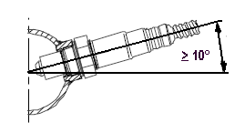
Mark a location on the exhaust downpipe where all cylinder pipes join, as close to the engine as practicable. Exhaust gas from every cylinder must pass over the sensor. Remove the downpipe, drill a hole at least 12 mm in diameter and weld on an M18×1.5 nut no more than 8 mm high. Screw the sensor fully into the nut. Ensure that its protective tip is fully inside the exhaust pipe and that the weld has no through-holes. Position the nut so that there is at least 15 mm clearance between the sensor and the vehicle body, and so that the sensor does not protrude downwards into the ground-clearance space. To prevent condensate entering the sensor, its axis must point upwards at least 10° from horizontal.
3. Warnings
3.1. Electrical measurements.
Do not connect an ohmmeter to oxygen-sensor signal wires, which may be black, grey or purple. Do not short them to the body or to live wires: the sensor may be damaged. If measurement is necessary, use only a voltmeter with an input resistance of at least 10 kΩ.
3.2. Conditions that may damage the sensor:
Leaded petrol or petrol containing additives.
Two-stroke engines running on a petrol/oil mixture.
Diesel fuel.
Nitromethane.
An excessively rich mixture.
3.3. Sensor ageing.
The normal service period before significant characteristic changes is approximately 450 hours, equivalent to about 20,000 km in an average vehicle. This does not mean the sensor becomes inoperative after that period: it may remain suitable for conventional threshold-based engine control. However, changes in its characteristic significantly affect Alfametr measurements. With an old sensor the display may indicate a leaner mixture than is actually present, especially below λ 0.95 and above λ 1.05. The error depends on the actual sensor condition.
3.4. Response time.
For internal-combustion-engine mixture indication the readings are practically instantaneous. For other applications, allow for a display delay of 0.1–0.3 seconds. The delay increases with the distance between the exhaust valve and the sensor location.
4. Use and practical guidance
4.1. Warm-up.
The oxygen sensor starts working when its sensing element reaches 350°C. After switching on, allow sufficient time for full warm-up. A one-wire unheated sensor must reach operating temperature through exhaust heat. A heated sensor such as the recommended BOSCH 0 258 005 247 normally warms up in approximately 0.5–1 minute after engine start.
4.2. Temperature influence.
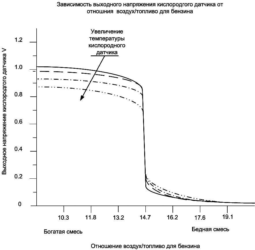
The oxygen-sensor output voltage depends on temperature; the graph shows the approximate relationship. This is most evident below λ 0.95. At operating points near maximum power, when the exhaust pipe is very hot, the instrument may show a slightly leaner mixture than is actually present. The size of the error cannot be predicted because it depends on the sensor's distance from the engine, exhaust-pipe insulation and the amount of fuel still burning in the exhaust. Ignition advance and enrichment therefore also influence it.
4.3. Closed-loop engine control.
When the sensor provides feedback to engine management, the display follows the control strategy. Normally it continuously switches between lean and rich regions, which is standard behaviour for most systems. During acceleration with active throttle opening the mixture becomes rich; during engine braking it becomes lean. In these conditions Alfametr acts primarily as an indicator of engine-management operation rather than a steady-state measuring instrument.
4.4. Sensor disabled or not used.
If the oxygen sensor is disabled in software, the engine-management system is designed to operate without it, or the vehicle uses a carburettor, use the recommended BOSCH 0 258 005 247 sensor. Alfametr is calibrated with this sensor. With a new sensor, the manufacturer specifies a measurement accuracy of ±7% or better.
4.5. Fuelling adjustment.
The instrument is principally intended for tuning petrol-engine fuelling. Carburettor jets are adjusted on a carburetted engine; software calibrations are adjusted on an injection engine. Because the instrument indicates the current mixture, it can assist with almost every operating mode, provided the operator knows which jet or calibration is active. For example, initial acceleration enrichment in a carburettor comes from the accelerator pump and is then followed by the main and progression circuits. The operator must define the target, measure progress and assess whether the adjustments move towards it.
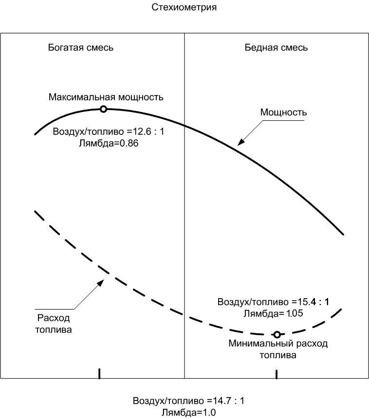
A multi-gas analyser offers a more comprehensive assessment of combustion, but its slow response, servicing requirements, cost and size make in-vehicle use and measurements outside static conditions difficult. Spark-plug insulator colour provides an averaged and approximate result, and only when the plug heat rating is appropriate. An oxygen-sensor-based instrument is useful despite the limitations of indirect measurement. Alfametr measures oxygen content rather than all exhaust constituents; oxygen is particularly informative for estimating excess-air coefficient. The required enrichment depends on the tuning objective. The graph illustrates the qualitative relationship between power and economy under otherwise equal conditions.
4.5.1. Fuel economy.
Aim for a coefficient close to 1–1.08 during driving, except during acceleration. For economical acceleration, the accelerator pump or its software equivalent initially provides a deliberately rich mixture, after which enrichment is reduced gradually to the boundary at which acceleration remains free from hesitation. The acceleration coefficient is individual to each engine and cannot be specified universally.
4.5.2. Maximum-power mixture.
The stated target range is 0.82–0.89. Exact measurement in this range is limited by the unpredictable high temperature around the sensor. In practice, fuel consumption is secondary when tuning for maximum power, and within the rich region the engine is relatively insensitive to further enrichment. The manufacturer considers a consistent reading below 0.95 and above 0.8 sufficient for this purpose. Fuel also cools the combustion chamber, so slight enrichment is preferable to excessive leaning; it can reduce the tendency to pre-ignition and detonation when hot without sacrificing torque.
4.5.3. Idle mixture.
Do not make idle excessively rich, irrespective of the tuning objective. This causes soot deposits and resulting ignition irregularities. At high-power operating points, higher temperatures clean the spark-plug electrodes and insulators, so the same soot mechanism does not normally occur.
4.5.4. Economy/power compromise.
On a twin-choke carburettor, one approach is to tune the first chamber for economy with the second-chamber linkage disconnected and the second throttle held closed. Select first-chamber jets during test drives, then reconnect both chambers and adjust only the second-chamber jets to obtain the desired full-throttle power mixture. The injection-engine equivalent is to separate economy and power calibrations according to engine speed and throttle opening, as used by most engine-management systems.
4.6. Unexpected or apparently incorrect readings.
Engine faults can make oxygen-based mixture readings misleading. With an intermittently firing cylinder caused by a failed spark plug or lead, unburnt oxygen enters the exhaust and may be interpreted as a lean mixture even when the actual fuel mixture is not lean. Excess oil entering the combustion chambers consumes oxygen during burning and deposits a film of burnt and unburnt material on the sensor, which can also produce a misleading lean indication. Very late ignition can allow fuel to finish burning in the exhaust and overheat the sensor, so that an excessively rich mixture is displayed as only slightly rich.
An injector delivering too much fuel can create an uneven mixture between cylinders. Adjusting solely to the averaged oxygen reading may then make the other cylinders excessively lean. An injector that does not open can produce effects similar to a non-firing spark plug.
4.7. Fuel-pressure regulator check.
Disconnect the regulator vacuum hose at idle: the mixture should become richer.
4.8. Injector balance check.
At idle, disconnect the injectors one at a time and record the change in Alfametr reading. Equal injector delivery should produce equal changes.
4.9. Air-filter check.
For systems without an airflow meter, compare full-load readings with and without the filter. A leaner mixture without the filter indicates that the filter introduces restriction.
4.10. Long-duration camshafts.
At idle, engines with long-duration camshafts can show a very lean reading despite running normally, because of valve overlap and poor cylinder scavenging. Readings should normalise as engine speed rises. In these cases use a multi-gas analyser to set idle mixture. Assessment of tuning quality remains the responsibility of the person making the adjustments and must draw on knowledge and experience. Alfametr readings are one important factor among several, rather than a complete basis for the decision.
5. Exhaust sampling pipe
The instrument can be used with a sampling pipe inserted into the tailpipe from behind the vehicle, with the oxygen sensor facing upwards. Insert the pipe fully up to the sensor nut and secure it with a clamp.
Idle sampling limitation.
At idle, low-pressure waves can draw outside air into the exhaust. Because the sampling pipe does not seal the tailpipe and cannot have the same effective length for every vehicle, the instrument may indicate a leaner mixture than actually present. At higher speed and load the exhaust stream becomes continuous and readings normalise. For idle adjustment use a stationary gas analyser or a sensor in the original mounting location. The external section of the sampling pipe may be extended with a hose at least 0.8 m long and the joint between the pipe and exhaust sealed; this can normalise the idle reading.
Sensor limitation.
With any sensor other than BOSCH 0 258 005 247, the measurement range and accuracy stated by the manufacturer are not guaranteed. The instrument reliably identifies λ equal to 1 and the rich and lean regions.

 We perform fast worldwide shipping and PayPal payments
 We provide a guarantee for products and technical support
 Our system of discounts and regular promotions save your money